If you are a current student, please Log In for full access to the web site.
Note that this link will take you to an external site (https://shimmer.csail.mit.edu) to authenticate, and then you will be redirected back to this page.
1) Switches
In a previous exercise you derived and studied the equations for a *very common* circuit: the voltage divider:
We can build a lot of cool, useful circuits simply by building upon this basic voltage divider circuit. For example, we can replace one of the fixed resistors with a device whose resistance varies with some external signal. As a result, the circuit becomes a transducer, which is a circuit that converts one form of signal into another.
2) Pull-Up Switch Configuration
When integrating a switch into a embedded system, we've exclusively been connecting one side of our switch to ground (0V) and then one side to a digital input. This forms an active low switch (provides readings of 0 when pushed and 1 when unpushed).
But this raises an interesting question...when the switch is connected to an input (something which makes electrical measurements) we can clearly see that when the button is closed, the input is connected directly to ground (0V)...

...but what happens when the switch is open? You might say well it is a "High" voltage (whatever the opposite of 0 is in our digital way of life), but is it really?
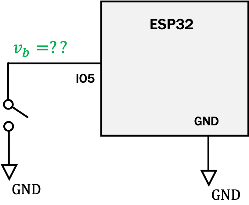
The truth is that when the switch is open, it ties the digital input to nowhere. By nowhere, we mean the voltage that will be present on that input terminal is undefined. It could be high and it could be low. Because of the electrical nature of the digital inputs (very, very high input resistance), it also means that they are highly susceptible to parasitic charges and voltages...so something like you touch the wire or simply radio waves or static electricity could potentially come in and define the voltage on the line since the button sure isn't doing it.
This is problematic since we have no deterministic way of measuring the button's state. For example if we get a reading from the button we have to use the following logic to deduce what it means:
- 0 when pushed
- 1 or 0 when unpushed
There is catastrophic ambiguity in this...basically just enough to make any reading completely useless. This is no way to go through life.
The solution comes from what we do when we set up the digital input. In our setup function, you'll see that we've always been doing something like this:
pinMode(5, INPUT_PULLUP);
What that second argument does is tell the ESP32 to configure that input so that in addition to being connected to the outside world it is also connected to an internal resistor tied to 3.3V (Digital High Voltage)

This pull-up resistor R_{PU} defines the voltage at the input when we aren't pushing the button...basically it provides a default. Drawn in a more theoretical way our switch circuit now looks like the following (note that v_{out} is "out" from the perspective of the switch...it would be the input voltage signal from the perspective of your ESP32).
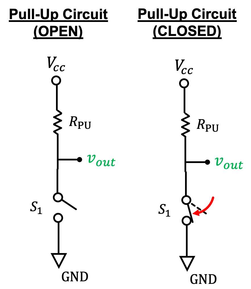
We can derive how this type of circuit works by falling back to our voltage divider circuit from previous exercises. If we think about the switch as a variable resistor with the following qualities:
Substituting in the closed and then open resistance we can derive two output voltages for the closed and open cases, respectively:
Yay so this alligns with what we've seen. When the switch is open, the output voltage is HI (the voltage V_{cc}) and when the switch is closed, the output voltage is LO (0V).
In practice pull-up resistors will be on the order of several 10's of KiloOhms.
3) Python Implementation
Let's model our pull-up active low circuit with a Python function pull_up that takes in three inputs (in order):
vccThe value of V_{cc} in a pull-up circuitrpuThe fixed pull-up resistor value in the circuitswitcha boolean variable, whereTruemeans the switch is closed andFalsemeans the switch is open
The function should return the output voltage within 1% of the actual answer, and must make use of the previously defined function voltage_divider from the earlier exercise last week A working version of voltage_divider has already been imported for you in the code boxes below so you should not rewrite/reimplement your own!!!!
One thing you'll realize in doing this problem is that there's no real easy way to represent the number "infinity" in Python. Instead as an effective substitute, have your function pick a number that would basically act the same as infinity....maybe a value that is a certain number of times larger than the r value, for example.
voltage_divider for every possible input

4) Pull-Down Switch Configuration
When most people first encounter a pull-up circuit with an active low switch they have an existential crisis because we are taught that "1" should mean "on" and "0" should mean "off." Based on the math above, you should be able to do the opposite of a pull-up resistor as well. A pull-down. This is true, it can be done, but it is much more rare.
A pull-down circuit which would provide an active-high signal would look like the following:
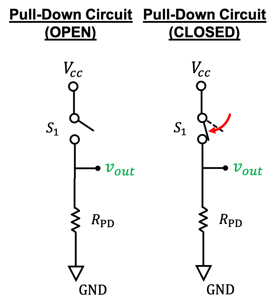
Similar math to what was done above could show that this will provide:
- High/1/3.3V when pushed
- Low/0/0.0V when unpushed
5) Python Implementation
Write a Python function pull_down that takes in three inputs (in order):
vccThe value of V_{cc} in a pull-downcircuitrpdThe fixed resistor value in the circuitswitcha boolean variable, whereTruemeans the switch is closed andFalsemeans the switch is open
The function should return the output voltage within 1% of the actual answer, and must make use of the previously defined function voltage_divider from the earlier exercise. A working version of voltage_divider has already been imported for you in the code boxes below so you should not rewrite/reimplement your own!!!!
Again, one thing you'll realize in doing this problem is that there's no real easy way to represent the number "infinity" in Python. Instead as an effective substitute, have your function pick a number that would basically act the same as infinity....maybe a value that is a certain number of times larger than the r value, for example.
voltage_divider for every possible input
6) Why Active Low???
It seems so opposite of what we want to think of as humans, but in truth it doesn't really matter, does it? A rose by any other name... As long as we know how to interpret it, we can have things work the same. For many different reasons, which are beyond the scope of 6.08, and which get touched on in courses like 6.012 or 6.004 or 6.111, active-low switches with pull-up resistors remain the norm in electronics:
- It is arguably safer to tie inputs of microcontrollers directly to ground rather than a supply voltage of possible unknown value. In active low/pull-up they're at least tied through a resistor to VCC
- Some older logic families worked only and/or more efficiently in an active low format
- Pull-up resistors/active-Low setups allow easier interfacing between logic chips running at different voltages (under some conditions)
- In addition to our regular digital electronics scheme, there is also a family of electronics/communications that are "tri-state" and pull-up resistors are more compatible with this for reasons we won't go into.
The ESP32 has internal settings to enable either pullup or pulldown resistors when specifying digital inputs (with the exceptions of pins 34 to 39 which you should just not touch anyways). If you're really disgusted by this, go ahead and use INPUT_PULLDOWN when instantiating your inputs, just remember to wire your buttons correctly.