If you are a current student, please Log In for full access to the web site.
Note that this link will take you to an external site (https://shimmer.csail.mit.edu) to authenticate, and then you will be redirected back to this page.
We'll now study/derive/analyze/play with one primary type of circuit: The voltage divider. In order to figure this circuit out, however we need to run through some more basic circuit theory first.
In last week's exercises, we studied circuit network theory, the idea that components when connected together are subject to two major laws:
- Kirchoff's Voltage Law: The voltage around any closed loop in a circuit must sum to zero
- Kirchoff's Current Law: The currents into any junction in a circuit must sum to zero
Given a network topology and sufficient starting information, it should always be possible to define the voltages across and the currents through all components in any circuit.
1) Resistors
Many components constrain/dictate how the current through them and the voltage across them are related, and this can further dictate what a circuit settles at when built. One part we'll consider today is the resistor.
In schematic form,1 resistors take on the form of a zig-zag:
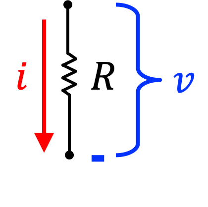
A resistor asserts that the voltage across it, v, is proportional to the current through it, i, times its Resistance, R (measured in Ohms). Many people learn Ohm's Law, and believe that as long as you violently shout "V = IR" then you'll be good, but there's more to it than that. The direction/orientation really, really matter. As we've drawn it in the figure above, Ohm's Law states:
What Ohm's Law tells us is that current (i) will flow from areas of high potential to lower potential. If v is positive that means that i will also be positive. If v is negative, that means i will also be negative.
We can also draw out a resistor and state Ohm's Law in terms of node voltages (again a concept introduced last week):
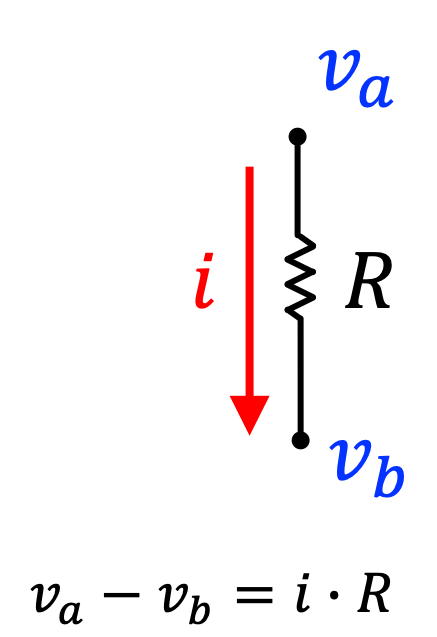
Here Ohm's Law would be written as:
The two v variables represent electrical potential (which we often call voltage) at the top "node" and bottom "node". If the voltage at node A, v_a is larger than the voltage at node B, v_b, that means current is going to be positive. If v_a is lower than v_b, then the current i will be negative.
If v_a =14\text{V}, v_b=5\text{V}, and R=219\Omega, what would current i be (in Amps)?

Now, what if v_a =-14\text{V}, v_b=-5\text{V}, and R=219\Omega, what would current i be (in Amps)?
This should emphasize a really important point that i can be either positive or negative. What does it mean for i to be positive? You just need to think of i as a frame of reference2
2) Ground
When working with node voltages, we need to define one node as being 0.0 Volts. We'll often call this node the ground of our circuit.
When we define one node as ground, we then define all other voltages with respect to that ground node. So if you had a circuit where v_1 = 11\text{V} and v_2 = 2\text{V} and we decided to define the v_2 node as Ground, what would we now say the voltage at v_1 is (in volts)?
And what would the current through that resistor connected to nodes v_1 and v_2 be if R = 50\Omega and current is defined as going from node 1 to node 2(in Amps)?
Now what if we had a circuit where v_1 = 2\text{V} and v_2 = 12\text{V} and we decided to define the v_2 node as Ground, what would we now say the voltage at v_1 is (in volts)?
And what would the current through that resistor be if R = 50\Omega (in Amps)?
A lot of times when you have a fixed positive voltage we call it V_{cc}. In many of our ESP32-based circuits our V_{cc}=3.3\text{V}, for reference. A resistor going from V_{cc} to ground could therefore be drawn like so:
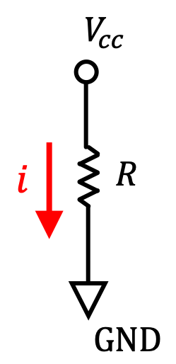
What would the current i be in the circuit above if V_{cc}=3.3\text{V} and the resistance R is 380\Omega? Just to make life interesting provide your answer in milliAmps.
3) Voltage Divider
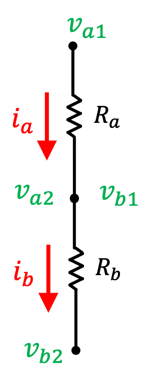
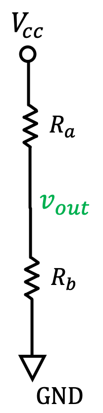
OK, now what happens when you connect two resistors in series like what is shown below? Let's define everything for the top resistor with underscore a and everything with the bottom resistor with underscore b. Drawing it out and labeling gives the following
Let's redo our math from earlier for each resistor.
Current flowing through R_a (downward) must equal the current flowing through R_b (downward). This should sort of be intuitive from looking at this figure and this is known as Kirchoff's Current Law. We'll call this common current i_{total}.
When we substitute these new insights into our we get:
Let's now assume that we're in a more specific circuit situation where our bottom voltage (v_{b2}) is actually at GND, which means we can call it 0. Also let's assume that our top voltage v_{a1} is now just V_{cc}. Further, the voltage v_{mid} can be called v_{out}.
The two equations above become:
Shuffling the second equation around so that it expresses:
which can be rewritten as:
Then rearranging so our equation is more like
This is known as the voltage divider equation and is extremely versatile since it fully describes the voltage divider circuit above.
Yes, it looks very simple and its math is very simple, but we can do many things with it, and we'll use it in coming labs and homeworks.
4) Practice
Use the voltage divider equation to solve specific cases of the voltage divider circuit below.
What is the output voltage v_{out} (in Volts) if V_{cc}=6V, R_a = 1\Omega, and R_b=5\Omega?
5) The Voltage Divider and Programming
Doing the same math again and again repeatedly gets boring. We've been doing lots of C++ programming. Just to keep the Python muscles limber, let's use some Python to write a function that will do the math for us. Define a functionvoltage_divider that takes in three inputs vcc, ra, and rb and returns the output voltage $v_{out}$ in Volts.
6) Next Steps
We can now use the voltage divider circuit to generate many types of sensor circuits. By replacing one of the "fixed" resistors with a device who's resistance varies as a function of some external signal (heat, light, touch, whatever), you can have a circuit that with input. This forms what we call a transducer. For example in the circuit below, the resistance of the lower element is a function of light. As a result, the voltage out v_{out} is a function of the light! The ESP32 can measure this voltage using a call to analogRead(which we'll talk about in future weeks).
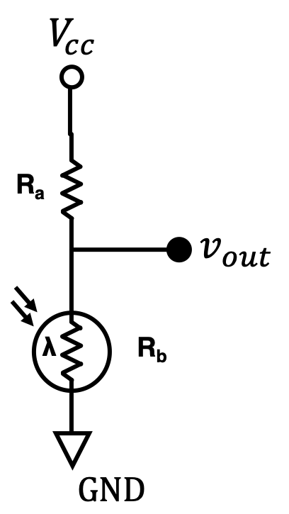
In circuits like these it'll actually is productive to use the voltage divider in a backwards form (and this is where our understanding of this circuit becomes really useful. We'll be getting readings of the voltage V_{out} and we'll need to use those to extract what value R_{sensor} (R_b) is in order to use that to figure out the temperature, amount of light etc...
So give this a try real quick: What must the value of R_b be (in Ohms), if V_{cc}=11V, R_a = 7.00\Omega, and V_{out}=7.50V?
Now create a function resistanceExtractor. It should take in three values, vcc, ra, and vout, correspondign to V_{cc}, R_a, and v_{out}, respectively, .and return back the calculated value of R_b.
Footnotes
1In the US, anyways, in many other countries a box is used...I'm looking at you UK.
2Do not dismiss the fact that sign is important. If someone told you that your bank account changed by either positive or negative $1,000,000 the sign would really matter to you. Same goes for voltages and currents! Moreso even. Money can't buy happiness, but voltage and current can.