If you are a current student, please Log In for full access to the web site.
Note that this link will take you to an external site (https://shimmer.csail.mit.edu) to authenticate, and then you will be redirected back to this page.
1) Starters
We'll be working with circuits in 6.08. Therefore we first need to quickly establish the quantities and measurements we'll be dealing with in circuits. A lot of times words like "power", "energy", "voltage" etc... get thrown around a lot to varying degrees of technical correctness, but it is important to remember that they have very specific meanings.
1.1) Voltage
The units of voltage are Joules per Coulomb or J \cdot C^{-1}, and you can think of voltage as an energy differential that affects charge particles. Voltage is measured in units of Volts, and in our circuit we'll often find it convenient to deal in either just Volts (\text{V}) or milliVolts (\text{mV}), thousandths-of-a-volt, as needed.
Voltage is an inherently differential measurement. It is a description of an energy differential between two points in space. So when somebody says something like "9V" for example, it really means that there are two spots that have a 9V potential between them, and that the energy differential is such that if there was one Coulomb of electrical charge separated between those two points, it would have 9 Joules of energy. A standard USB A or USB B cable can provide 5V for powering devices, and what this means is that it has two wires, which have a 5V potential between them.
There is no universal 0V point so a voltage must always be between two points! In the case of the numerous mobile objects which surround us in our daily lives,those primary two points in question are the two terminals of a battery. In the case of electronics plugged into the wall, it is the between the two slot-shaped sockets (when in the US), one of which is usually at a similar potential to the earth (though not guaranteed).
We will discuss a shortcut/notation that makes life a bit easier later in this page, but this is a very important point to remember!
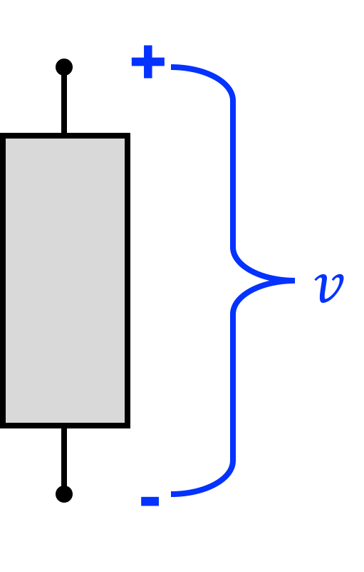
If we had a device (represented by a grey box) and defined a voltage across it as v, what we're saying is that going from the + end to the - end there is an energy differential which we describe as v.
1.2) Current
Current is the flow of positive charge. Even though the charge carriers through most conductors are electrons (and electrons have a negative charge), because of some historical issues we're stuck with current being defined as the flow of positive charge...sort of like the Electoral College. Anyways, current is specified in units of Amperes or "Amps" (A), however in many mobile devices this is actually a relatively large amount of current and we'll often deal with either milliAmps (mA) or microAmps (\mu A), which are of course thousandths and millionths of an Amp, respectively. An Amp is related to charge by the equation:
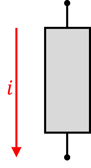
In the context of a device we can say that i is the current through it:
1.3) Electrical Power
If Voltage has units of Joules per Coulomb and Current has units of Coulombs per second, we can maybe see that there might be some cancellation action going on if we put these two measurement together.
In particular if the voltage across a device (represented by a grey box with two wires proceeding out of it) is called v and the current through a device i are defined as the following
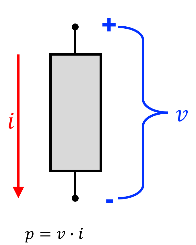
We can say that the power consumed by the device is equal to the produce of the voltage and current or:
A quick unit analysis reveals that this works out to be:
where "Watt" is a unit of power defined as a Joule per second. A Watt is actually a lot of power so we'll often be measuring our power consumption in thousandths of a Watt or milliWatts (mW).
In the circuit above, if v = 8 \text{ } V and i=2\text{ } A:

1.4) Importance of Sign
It cannot be stressed enough that in the above power calculation, the sign of the current and voltage and how we defined their direction was critical. Power can be calculated to be both positive and negative and the sign of the power term has profound implications on determining parts of a circuit, so you must remember this.
This equation only applies when the voltage and current value being multiplied are defined with respect to how they are shown in the image below:
Confused on this? That's ok, we'll try to hammer this home as we talk about our circuits laws below. Just remember that the i and v values we have specified above are really just frames of reference that have no bearing on what is happening in the real world. They only affect how we interpret the real world.
2) Circuit Laws
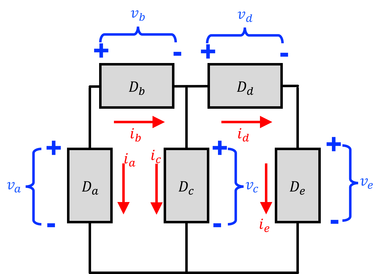
Analyzing the power through one component is fine, but when you starting getting networks of components and devices each with their own voltage across and current through them like the following, we need to generate and utilize rules that indicate how currents and voltages are related to one another and consequently figure out how their powers are related to one another.
In order to do this we're going to go over two major circuit laws in this set of notes and problems:
- Kirchoffs Current Law: The sum of currents into a junction must sum to 0
- Kirchoff's Voltage Law: The sum of voltages around any loop in a circuit must sum to 0
As we investigate these terms keep in the back (front) of your head that sign is really, really important in this stuff and makes all the difference between getting right and wrong answers!
3) Kirchoff's Current Law
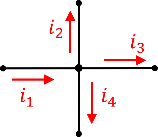
Kirchoff's Current Law (KCL) says the total sum of currents entering OR leaving a junction must be 0 or for the following diagram:
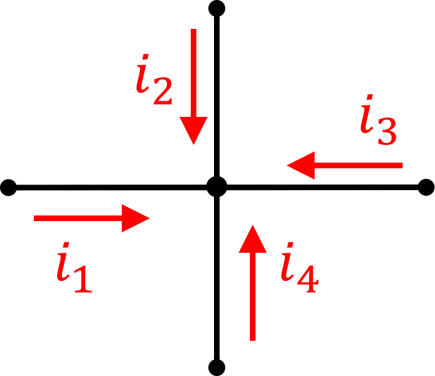
or in equation form:
or again in equation form:
Note that in both cases, the reference currents are defined as going all in or all out. In both situations, be can just say the sum of all must be zero.
With these reference current directions in mind, we can do:
| i_1 = | |
| i_2 = | |
| i_3 = | |
| i_4 = |
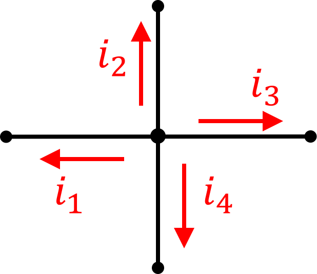
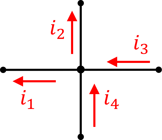
If we change how we define our reference currents we'll see the values associated with them change as well. Again take the electrical junction with measured currents below:
| i_1 = | |
| i_2 = | |
| i_3 = | |
| i_4 = |
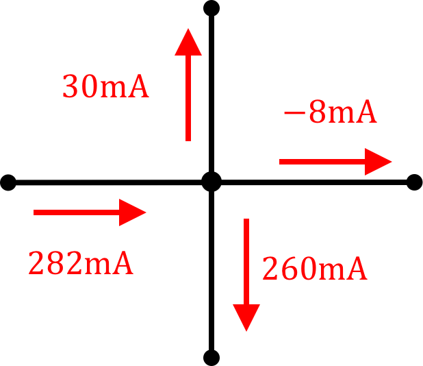
We can also reframe our Kirchoff's Current Law with mixtures of current references like the following:
In this case we can say that the sum of currents going in must equal the sum of currents going out, which for the example above says:
| i_1 = | |
| i_2 = | |
| i_3 = | |
| i_4 = |
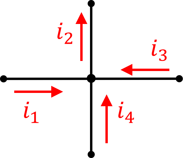
As more practice, given the circuit junction below:
i_8)
and again for this junction:
i_8)
4) Kirchoff's Voltage Law
The second big circuit law is Kirchoff's Voltage Law (KVL), which states that the sum of voltages around any loop in a circuit must be zero. In equation form this is represented as:
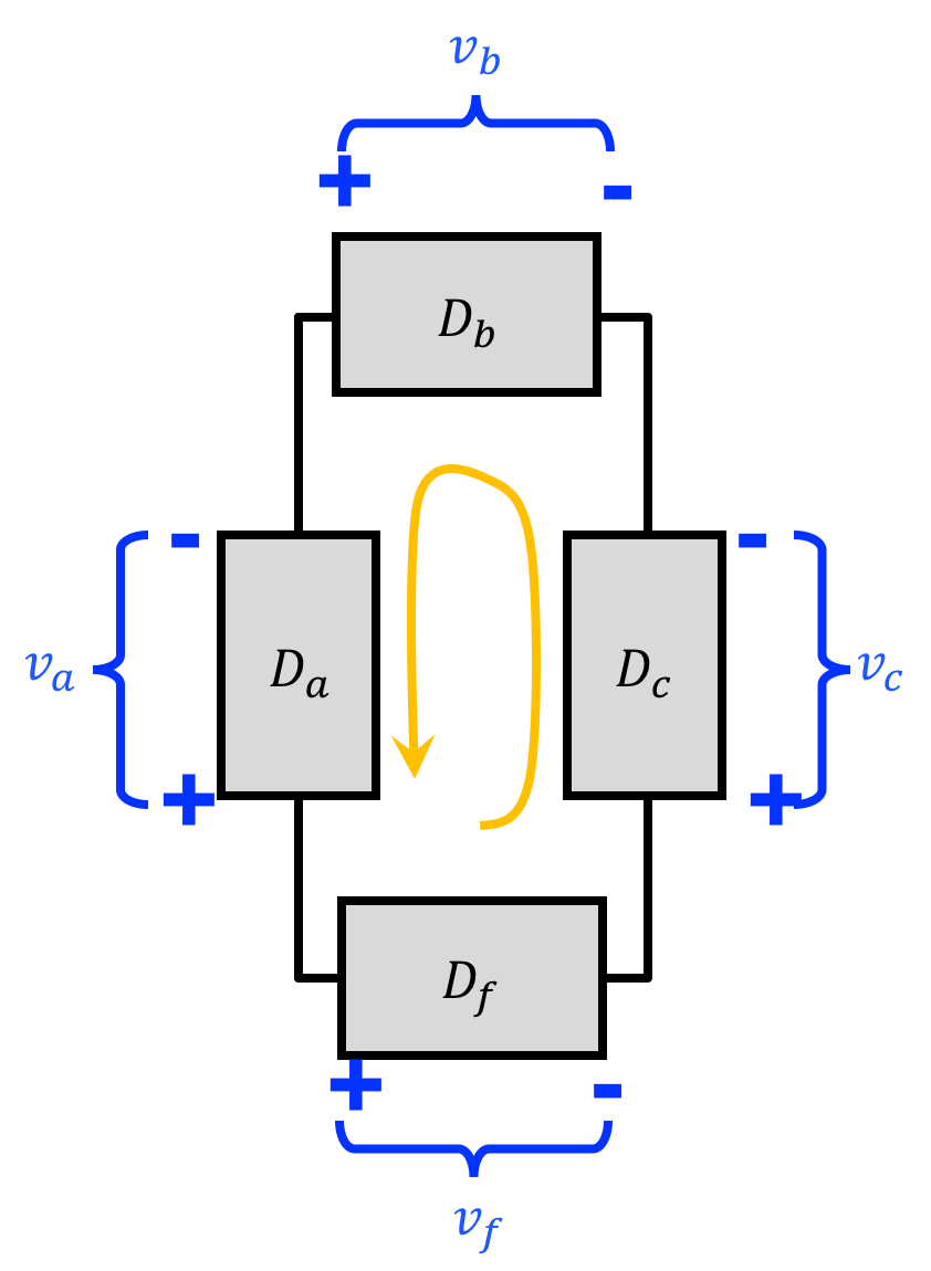
We get that by starting at any point in the circuit and marching clockwise around the circuit loop (following the orange arrow) until we get back to where we started.
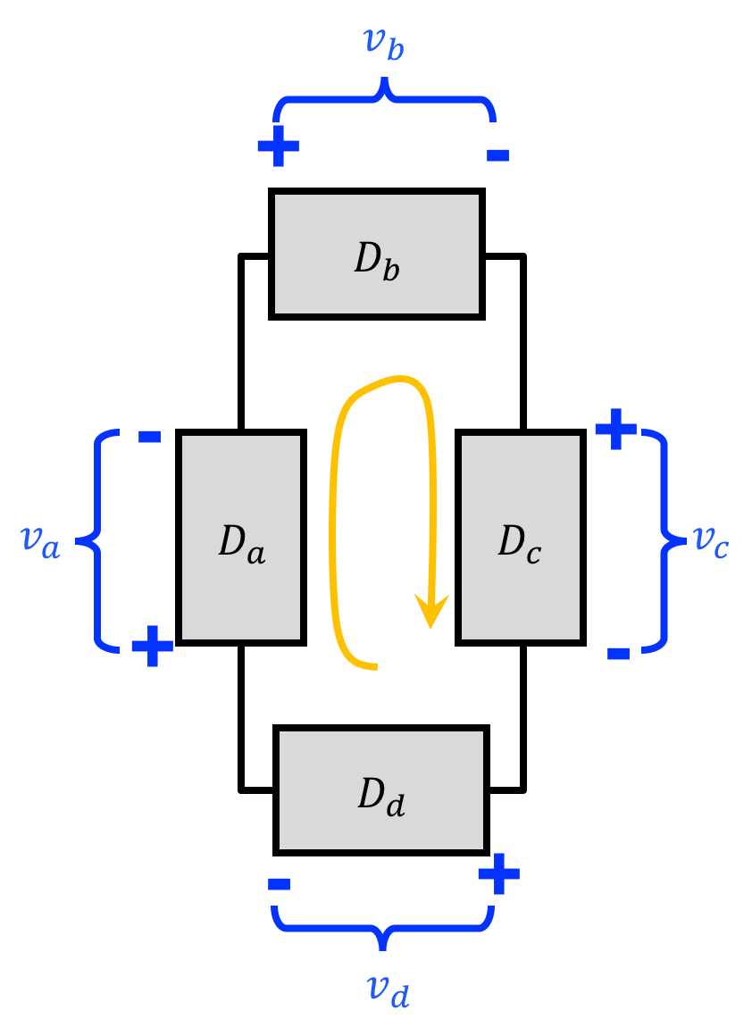
In the example above, what we did was sum up the voltage "drops" (the value of v which is from the + location to the - location) going around the circuit in a clockwise fashion. Just like with KCL, however we can also deploy this on setup where our reference voltages are flipped like so:
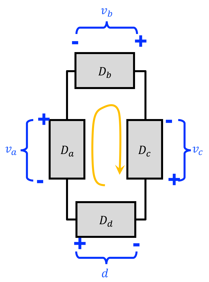
in which case we could arrive at a similar expression if we sum the voltage "jumps"
And just like in KCL we can deploy KVL when our reference voltages have an arbitrary direction specified:
But in this case we need to pay close attention to signs. Going around our loop in a clockwise fashion for the above circuit we'd come to the following equation:
The difference this time around is that in going through the loop the voltages are not all defined in the same "direction" as they were previously and so we need to keep this in mind. There are a few ways to systematically arrive at that equation. You could for example start in a spot and then while making your full circle loop (doesn't have to be clockwise...can be counter-clockwise as shown), set equal to 0 the addition of voltages whose "-" end you encounter first and subtraction of voltages whose "+" end you encounter first. Or you could do it the opposite: add voltages whose "+" end you encounter first and subtract voltages whose "-" end you encounter first. One will result in:
And these are mathematically equivalent. You just need to be consistent with how you treat the signs!
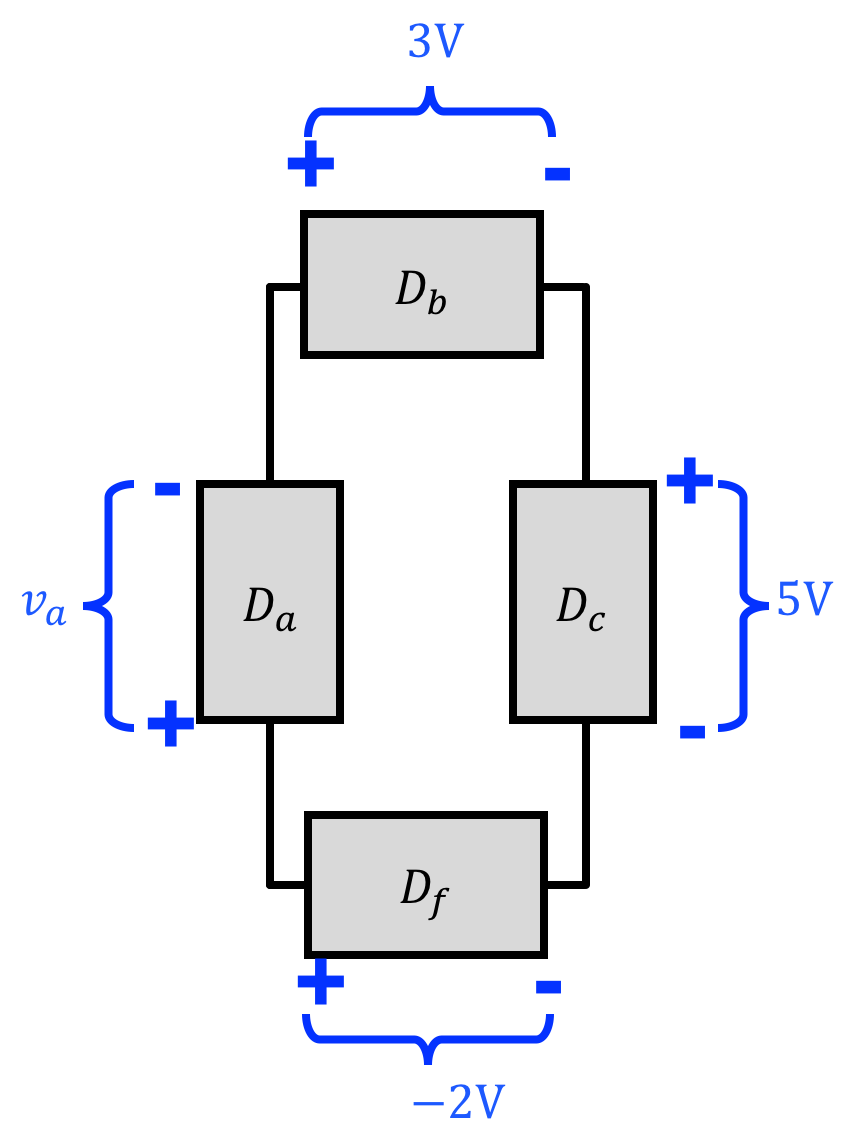
4.1) KVL Practice
Consider the following circuit:
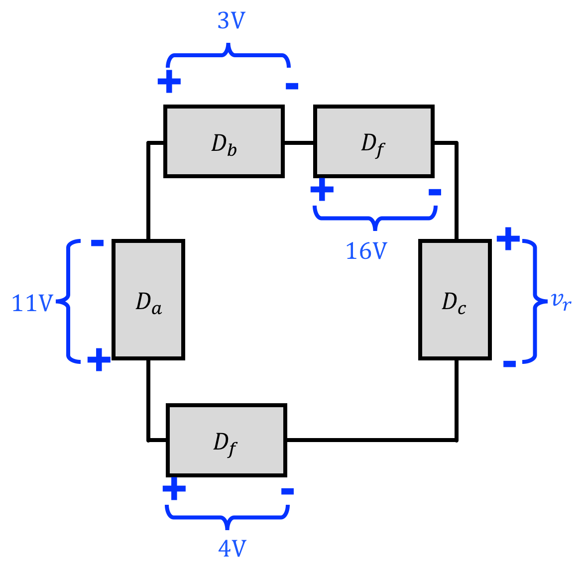
try another:
4.2) Node Voltages
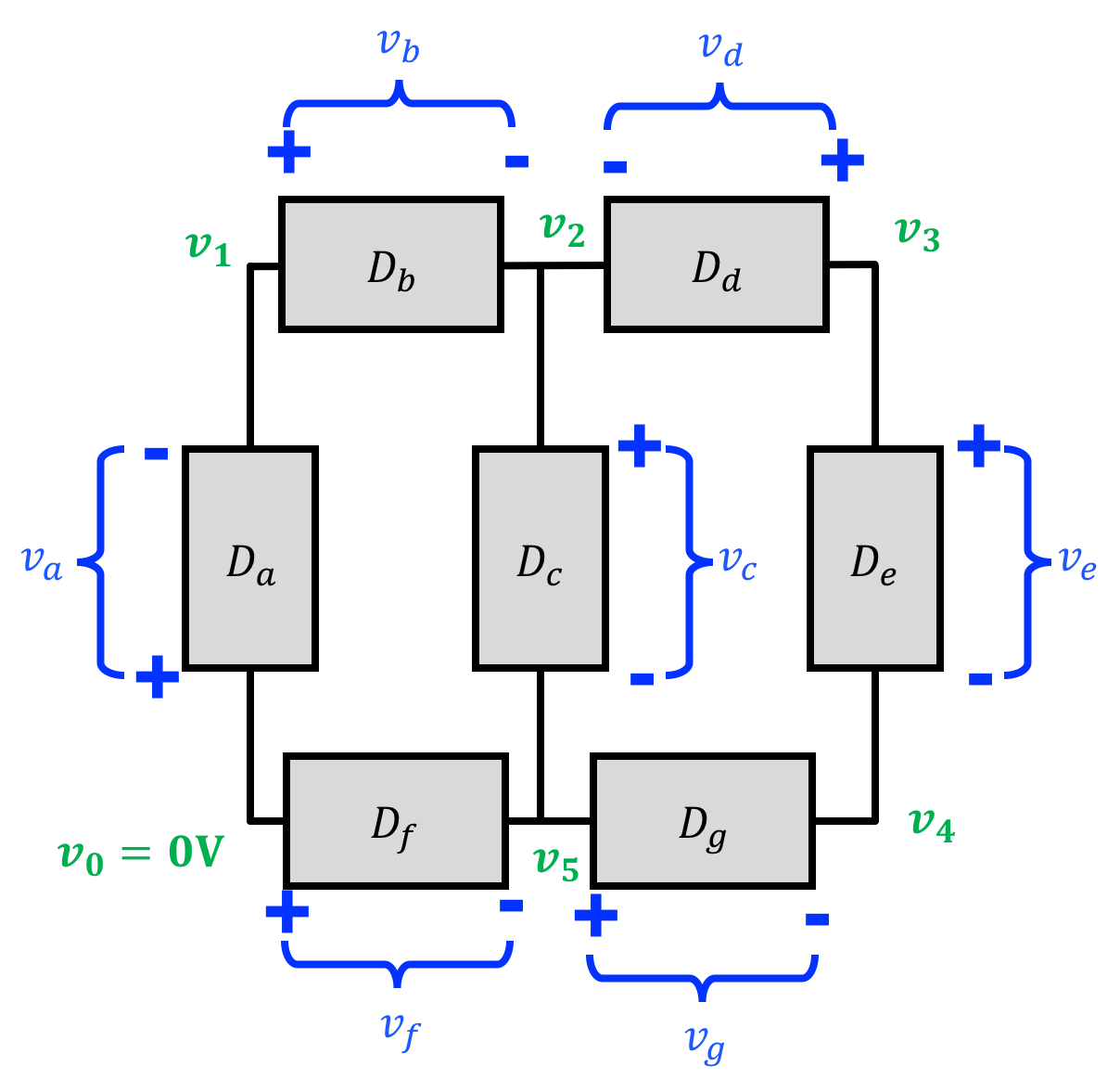
In practice, if we have a circuit with a bunch of components in it gets really annoying to have to specify the voltages across every node like shown below:
What we often do instead is pick a node (a node is wire location in the circuit) as our "reference node" and call it "0V" and then define every other node with respect to that like shown below:
Let's do all the others. Answer the questions below in terms of v_1, v_2, etc. Don't use v_0, use 0 (or omit it) instead.
i_8)
i_8)
i_8)
i_8)
5) Putting it All Together
With all the rules we've just gone over (KCL, KVL, passive sign convention), we can now solve for the power consumed by different components in a circuit. Do not be afraid if you end up with numbers that are negative. The value you calculate for power will have a sign and its sign is important (and we'll discuss the meaning in the next section). While keeping in mind sign and all that we just went over, solve for the power's consumed by all the components in the following three circuits.
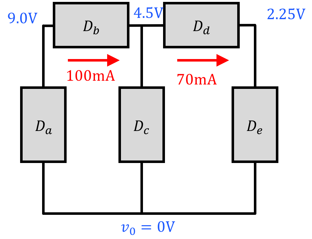
| p_a = | |
| p_b = | |
| p_c = | |
| p_d = | |
| p_e = |
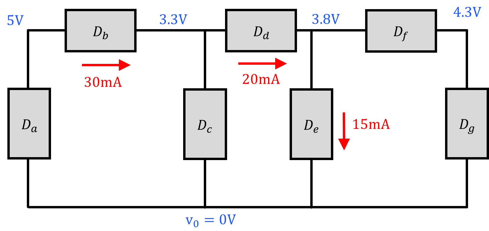
| p_a = | |
| p_b = | |
| p_c = | |
| p_d = | |
| p_e = | |
| p_f = | |
| p_g = |
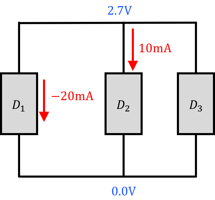
| p_1 = | |
| p_2 = | |
| p_3 = |
6) Sum of Power
You may have noticed above that once you generate all of your answers, the sum of the power terms in each case sums to zero! This is an important result because it emphasizes that the power (and by implication energy) is conserved in the circuit, and why we made such a big deal about being careful with our signs and following passive sign convention.
As it turns out, using the notation and conventions established here, if a device is found to consume positive power, that means it actually does consume power. Examples of objects which consume power are most of your system components (GPS, Wifi Module) as well as things like LEDs, motors, etc...
If the power is calculated to be negative this means that the device is supplying power. Things that supply power include power supplies (hence the name), batteries, solar cells, DC generators, etc.
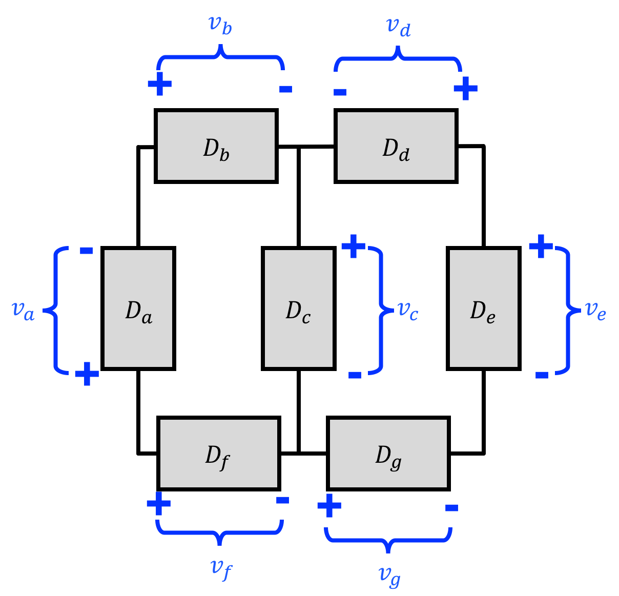
With this all in mind, solve for the powers consumed by all the components below:
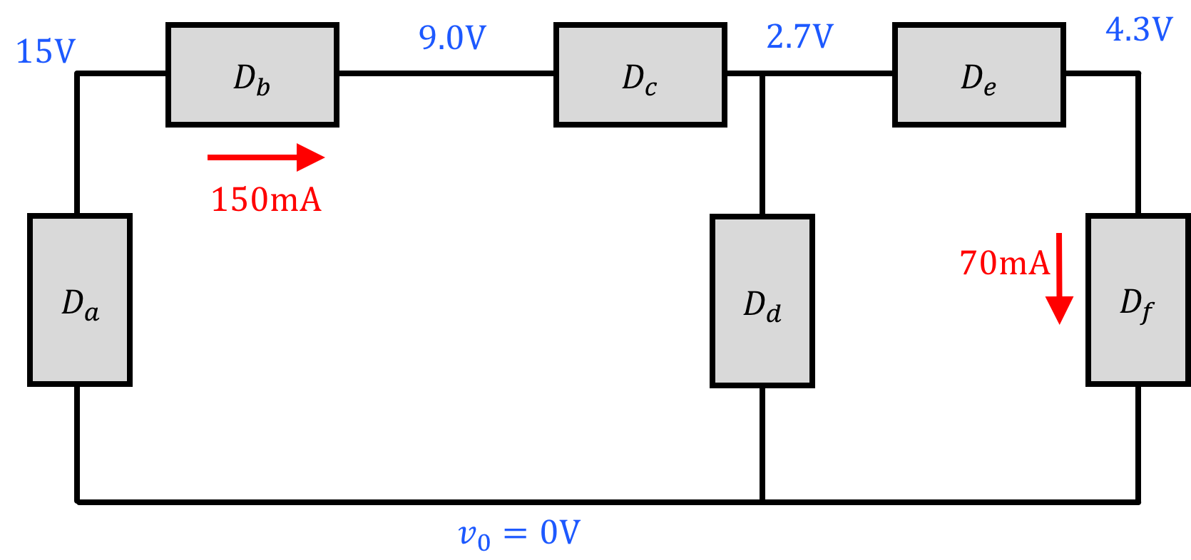
| p_a = | |
| p_b = | |
| p_c = | |
| p_d = | |
| p_e = | |
| p_f = |