If you are a current student, please Log In for full access to the web site.
Note that this link will take you to an external site (https://shimmer.mit.edu) to authenticate, and then you will be redirected back to this page.

1) Getting Started
Download two files for starters today. The IMU Library and some starter/demo code for today. Do the following for each folder (once properly extracted):
-
mpu6050_esp32: This folder contains a library that allows the ESP32 microcontroller to conveniently communicate with the IMU. To use this library, it needs to be manually placed into your*/Documents/Arduino/librariesfolder. Depending on your Arduino version you might need to restart Arduino before it will recognize the library. The library can then be accessed at any time in the future by including it at the top of your code:#include<mpu6050_esp32.h>. -
lab02a: This folder contains a minimal script to interface with the IMU that we'll use for visualizing the IMU's accelerometer data in real-time.
2) Adding the IMU
Grab the Inertial Measurement Unit (IMU) from your kit. The actual IMU is the small 4mm-by-4mm chip mounted in the middle of the blue circuit board. See the labkit page for visual reference. Everything else on the board is a support component. The IMU chip contains two types of sensors: a three-axis (x, y, and z) accelerometer and a three-axis gyroscope. The accelerometer measures linear acceleration and the gyro measures rotational velocity. This is an extremely powerful set of sensors all within a tiny chip (again, 4mm-by-4mm) that costs less than a dollar (~0.2 Bobas). We live in amazing times! In 6.08 we'll be using the MPU6050 IMU by Invensense. The data sheet is here for reference, and the register map for the device is here for reference.
For lab today and on Thursday, we'll be using only the accelerometer functionality. We'll use the gyroscope later on.
The IMU communicates with the ESP32 via the I2C (pronounced "I squared C" or "I Two C") communication protocol. It needs four wires going to it—two for power and two for the actual communication bus:

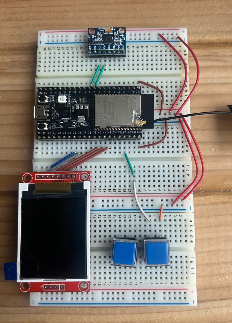
Place the IMU in the general area of your breadboard shown below. Again, as with everything we do, try to keep your wiring clean! Clean boards are happy boards. The image below shows the IMU location (however it doesn't show all the wiring)!
2.1) Reading Acceleration Data
Assuming you have already installed the IMU library (see the points on the files above if you haven't), open up lab02a.ino from the Lab's zip distribution. Let's look at the code in chunks prior to just running it:
At the top of the file, we import a library to interface with our IMU. This is the one we just installed and made you restart Arduino for:
#include <mpu6050_esp32.h>
At the global scope of our file we then create an object of the MPU6050 class which contains interfacing instructions for the IMU. By accessing this object, we will also be able to get measurements from it:
MPU6050 imu; //imu object called, appropriately, imu
In our setup we will do some stuff that should start to be looking familiar for us. This includes:
- Start up serial communications
- Initialize I2C communication (using the
Wirelibrary) for chatting with the IMU - Start up the IMU, check it is working,
- Start up the LCD, get that going
- Initialize a timer with a value
void setup() {
  Serial.begin(115200); //for debugging if needed.
  delay(50); //pause to make sure comms get set up
  Wire.begin();
  delay(50); //pause to make sure comms get set up
  if (imu.setupIMU(1)) {
    Serial.println("IMU Connected!");
  } else {
    Serial.println("IMU Not Connected :/");
    Serial.println("Restarting");
    ESP.restart(); // restart the ESP (proper way)
  }
  tft.init(); //initialize the screen
  tft.setRotation(2); //set rotation for our layout
  primary_timer = millis();
  tft.fillScreen(TFT_BLACK);
  tft.setTextColor(TFT_WHITE, TFT_BLACK);
}
The imu.setupIMU() function makes sure the IMU is connected and, if it is, runs a few initialization tasks.
Finally our loop which contains the body of our code:
void loop() {
  imu.readAccelData(imu.accelCount);
  x = imu.accelCount[0] * imu.aRes; //store convert x val in g's
  y = imu.accelCount[1] * imu.aRes; //store convert y val in g's
  z = imu.accelCount[2] * imu.aRes; //store convert z val in g's
  //Serial printing:
  char output[40];
  sprintf(output, "%4.2f,%4.2f,%4.2f", x, y, z); //render numbers with %4.2 float formatting
  Serial.println(output); //print to serial for plotting

  //redraw for use on LCD (with new lines):
  sprintf(output, "%4.2f  \n%4.2f  \n%4.2f  ", x, y, z); //render numbers with %4.2 float formatting
  tft.setCursor(0, 0, 4);
  tft.println(output);
  while (millis() - primary_timer < LOOP_PERIOD); //wait for primary timer to increment
  primary_timer = millis();
}
In the loop block, we use imu.readAccelData() to read new accelerometer data. That method will update a three-element array internal to the MPU6050 class, imu.accelCount, which contains the acceleration data for each direction (accelCount[0] for x-directed accel, [1] for y-directed, etc.).
If you look at the IMU breakout board, you'll see how the directions are defined. z is up/down, while x and y are forward and side. The data stored in imu.accelCount is a signed integer between -32768 and 32767. This is because the IMU has on-board a 16-bit Analog-to-Digital Converter (ADC), so it stores its measured (analog) values as 16-bit signed (digital) integers. Those integers can be translated back to acceleration values by knowing the range of the accelerometer. In our case, it is set to \pm 2 \text{g}, so that 32767 is approximately 2 \text{g}, where a \text{g} is the acceleration from gravity on earth's surface (so \text{g} = 9.81 \text{m}\cdot\text{s}^{-2}). That range can be changed by setting a variable within the IMU.
We can calculate the acceleration in \text{g}'s much more easily with lines like this:
x =imu.accelCount[0]*imu.aRes;
We multiply the raw value by the scale factor (imu.aRes). The variable imu.aRes is a really convenient scaling factor. Similar lines of code can get us from raw gyroscope readings to angular velocity (in degrees per second) when we need those later on.
The numbers we generate then have two things done with them. First, they are printed over Serial so that we can read them on the Serial monitor. In addition to just reading them, when you print lines of numbers separated by commas, you can:
- Close the Serial Monitor
- Open the Serial Plotter ( under Tools>Serial Plotter)
- Watch the signals in real time.
This can often give a better feel for a signal that you're investigating.
For future applications, you can always render your signals using comma-separated values printed to the serial port, which is what we're doing here:
  char output[40];
  sprintf(output,"%4.2f,%4.2f,%4.2f",x,y,z); //render numbers with %4.2 float formatting
  Serial.println(output); //print to serial for plotting
Note that the weird %4.2f parts are how to inject formatted numbers into a char array we're building. This is explained in decent detail here!
We also display our three acceleration values on the LCD for convenience, which we do by printing them through another simple utility print function defined here:
  //redraw for use on LCD (with new lines):
  sprintf(output, "%4.2f  \n%4.2f  \n%4.2f  ", x, y, z); //render numbers with %4.2 float formatting
  tft.setCursor(0, 0, 4);
  tft.println(output);
Do the values make sense? What happens when you move the system around, or change the orientation? What do the plots look like while you walk around? Does the orientation matter in terms of detecting the steps? Consider taking screenshots for discussions later on. Why is the z value at around 1 when the embedded system is flat on the table?
3) Inertial Navigation
There is a lot of interest in using IMUs for navigation. After all, from Newton's Laws, if we know acceleration versus time, we should be able to infer position, right? We do this in 8.01, so why can't we do it to figure out where we are over time? Since the IMU is measuring acceleration, we should be able to integrate twice and figure out the position...right?
Unfortunately, no.
The reasons we can't just integrate twice are the likelihood of offsets and drifts in the sensor's measurements. Put simply, if the acceleration values are off even a little bit from reality, then errors in position will compound proportionally to the square of time, because \delta x = \frac{1}{2}at^2. Even seemingly negligible amounts of drift can quickly accumulate when integrating. In addition, any noise in the measurement will compound similarly. And it just so happens that our IMUs do have an offset. Even when there is no acceleration, the IMU does not report exactly 0.000000 g. It is off a little bit. Even if you calibrated it at the beginning of its use and subtracted off the offsets, it would still develop an offset over time (due to temperature and other factors), and there is always noise that affects the values a little bit, so zero acceleration does not actually result in a true zero reading. All together, it means even sitting still we don't get zero values.
So that's why we don't use inexpensive IMUs for inertial navigation. (People do make very expensive IMUs for inertial navigation, that have much lower noise, offsets and drifts, but we're talking very expensive, like 10's of thousands of dollars for use on nuclear submarines and things, and even then they aren't perfect.)
3.1) Forget Orientation
You should see that steps (and really any sort of movement) results in peaks and troughs along various axes of our accelerations. Our goal is to count steps, but we don't want to restrict ourselves to having to hold our labkit in just a certain way. In order to make our ability to measure these walking peaks better, we'd like to instead just look at the magnitude of total acceleration from all three axes combined, which is actually what most fitness trackers do.
Download lab02a_assignment.zip, which has some code for the second half of the lab. This code is very similar to the starter code except a few additions:
- A
ZOOMfactor is applied to the incoming x, y, and z values of acceleration both to aid in viewing and to scale the numbers to meters per second per second. - There is a variable in the
loopfunction calledacc_magwhich will be plotted. Assign to this variable the magnitude1 of the total acceleration vector (from the x, y, and z acceleration vectors), and watch the plot as you (carefully!) place the system against your hip and walk around a bit. Are there features in the plots that indicate when a step occurs?
Finally, you may notice that the spikes in your system are a bit too spiky. One way to cut down on "noise" like this is to average the signal. Care must be taken in doing this, because, if you average too much, you'll completely ruin the signal— but the right amount of averaging can be shown (mathematically and in other actually legitimate ways) to remove unwanted types of signals. Now, instead of plotting the raw magnitude of the acceleration, run it through a three-way sliding average, which takes the current magnitude and averages it with the previous two magnitudes. Assign this value to avg_acc_mag. Two variables, old_acc_mag and older_acc_mag are declared at the top of the file for your global use. Re-open the plotter, and compare/contrast the averaged signal vs the raw signal. If you're lucky the run/stop button in the top right of the plotted will work for you (even if it is grayed out). If you're unlucky this button is broken and you'll have to manually stop the data flow. I do this by holding boot and tapping rst. Tapping rst again will restart your ESP.
Step counting is actually a pretty complicated topic, and while there are good implementations out there on phones and fitness trackers there is no "right way" to do it. Walking around with your breadboard or gently moving your IMU to mimic the motion of walking should reveal that the three dimensions of acceleration the IMU provides do seem to do something when you make steps. How could we go about processing those signals?
When it is working, ask for the checkoff below!
Show and discuss your acceleration plots and calculations with a staff member.
Now it's time to count steps.
4) Step Counter
Step counting is actually a pretty complicated topic, and while there are good implementations out there on phones and fitness trackers there is no "right way" to do it. Walking around with your breadboard or gently moving your IMU to mimic the motion of walking should reveal that the three dimensions of acceleration the IMU provides do seem to do something when you make steps. How could we go about processing those signals?
An easy first thing to do is to treat the three acceleration values as depicting a acceleration vector in three-dimensional space and to then derive the magnitude of that vector. (If you don't remember how to determine the magnitude of a vector, that's ok; look it up online). Once we have a magnitude of the 3D acceleration we only have one value to worry about which makes processing it easier. Then, one very simple step counting algorithm is to find peaks in the magnitude of the acceleration experienced by the device. Each isolated peak corresponds to a step. The goal then becomes to process our signal to first find peaks, and then count those peaks as steps. This is graphically shown below:

You can test your step counter by mimicking steps via gentle drops on a table, and once that looks good, by walking around with it and comparing the number of steps reported with the number of steps you actually took. You can carry your laptop around with you to power the wearable. Study the shape of the signal you're trying to extract step information from. The "whole-story" may not come just from finding peaks. There might also be a trough after a peak Perhaps a state machine that must progress through a peak, then a no-peak or a trough/valley sequence, before restarting could be one idea to experiment with. Use data/measurements to determine good thresholds and timeouts as needed! We've included a variable called state in the starter code to gently suggest a state machine approach to this problem! It will allow nice integration on Thursday in Lab02B. The problem is not very different from the button one from Lab01B.
You may need some math operations in order to carry out this lab. math.h should have you covered (and we've already included it in the lab02a_assignment code). While the ESP32 math.h is slightly different, this math.h doc is about in-line with what you can do (remember double is a higher precision float, so you can use float or int with it). Also watch out for integer division!
While you may find that delaying and taking long-apart measurements can get you to a decent response, we want to impose a limitation that you avoid halting the primary loop with time-consuming calls to delay. The loop's speed must stay at about 100 Hz so that we can integrate it with other code later on.

Ask for help! There are lots of right ways to do it (and even more wrong ways to do it!)
Demo your system counting steps and show your
step_count algorithm and discuss your approach with a staff member. Make sure to have your step count printed both on the LCD and in the serial monitor!
When done, go in peace. We'll pick this back up on Thursday and integrate it with some more state machines and a server and some other stuff...
Footnotes
1if you have three vectors in xyz space, what will the magntidue be?